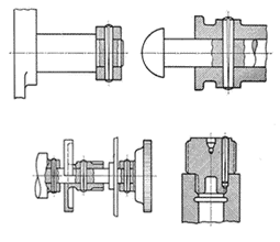
Universal Fastening System – The Grooved Pin Principle
The fastener incorporates in its design three longitudinal grooves swaged or formed into a cylinder of material, which has the effect of increasing its diameter. In the case of unheaded pins, this may be over part or all of the length of the pin and may be of a tapered or parallel form. In the case of headed pins, the grooves are always parallel and, with blind drive pin rivets, the pin is used to expand the rivet and is retained in the body of the rivet.
Groove compression
In each product, installation of the grooved pin causes the grooves to compress, this compression produces outward pressure on the walls of the hole and in so doing secures location of the pin. Diagram 1 shows compression taking place as a section through a grooved pin.
Simple, Reusable, Resistant to Shock and Vibration
When compared with more traditional taper pins, plain pins, keys, or locating pins, which rely on ‘interference’ at one point on the pin and also require a reamed or precision-formed hole, the grooved pin principle can be seen to represent a significant improvement. Resistance to withdrawal occurs wherever the grooved diameter is compressed; it can be over the whole length of the pin instead of just at one point as with traditional pins. This advantage is represented in diagram 2.

Why Use Grooved Pins?
|
Simple Hole Preparation
|
|
|
Resistance to Shock and Vibration
|
|
|
Total Range
|
|
|
They are Reusable
|
|
|
Simple Installation
|
|
|
Strength
|
|
Installation Information
|
Hole Preparation
|
|
|
Pin Strength
|
|
|
Installation
|
|
Installation Forces
These figures give data on the average installation forces required for tapered and parallel grooves. Generally the force to remove a pin is slightly more than the force required to install it.
Tapered Grooves – insertion force in kgs per length of groove
| Nom dia. mm. | 1.5 | 2 | 2.5 | 3 | 4 | 5 | 6 | 8 |
| 6mm | 23 | 30 | 37 | 64 | 95 | 132 | 223 | |
| 12mm | 50 | 64 | 82 | 128 | 186 | 255 | 418 | 609 |
| 18mm | 73 | 91 | 123 | 186 | 273 | 368 | 600 | 664 |
| 24mm | 94 | 128 | 164 | 255 | 364 | 482 | 770 | 1118 |
| 36mm | 523 | 686 | 1064 | 1518 | ||||
| 48mm | 682 | 891 | 1345 | 1918 | ||||
| 60mm | 2395 | |||||||
| 72mm | 2864 |
Parallel Grooves – insertion force per mm of groove
| Kgs | 9 | 11 | 13 | 17 | 22 | 28 | 40 | 55 |
Standard Tolerances
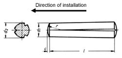
Body Diameter, dome and length
Tolerance on body diameter and dome
| Nominal d1 | 1.5 | 2 | 2.5 | 3 | 4 | 5 | 6 | 8 | 10 | 12 | 13 | 14 | 16 | 20 | 25 |
| d1 tolerance | +0.0 -0.025 |
+0.0 -0.075 |
+0.0 -0.090 |
+0.0 -0.110 |
+0.0 -0.130 |
||||||||||
| C max. | 0.23 | 0.3 | 0.4 | 0.45 | 0.6 | 0.75 | 0.9 | 1.2 | 1.5 | 1.8 | — | 2 | 2.5 | 3 | 4 |
d1 = Body diameter C = Height of dome L = Body Length
Tolerance on length ‘l’
| The Grooved Pin designs are subject to certain standard tolerances, which are listed here. Other specified tolerance information is provided is provided in our literature. |
1mm – 3mm
|
+/-
|
0.200
|
|
|
over
|
3mm – 6mm
|
+/-
|
0.240
|
|
|
over
|
6mm – 10mm
|
+/-
|
0.290
|
|
|
over
|
10mm – 18mm
|
+/-
|
0.350
|
|
|
over
|
18mm – 30mm
|
+/-
|
0.420
|
|
|
over
|
30mm – 50mm
|
+/-
|
0.500
|
|
|
over
|
50mm – 80mm
|
+/-
|
0.600
|
Product Identification
The part number is made up of the nominal diameter and effective length. The example shown here is for Grooved Pin S8 – third length center tapering grooves – DIN 1475. A standard part number assumes a plain steel material. Other materials should be noted at the time of specification by quoting the appropriate material reference.
Material Specifications
Grooved Pins, Headed Grooved Pins
The Tappex Grooved Pin system is manufactured in Germany, consequently material specifications relate to DIN standards. Various options are available and these are given below together with DIN reference numbers where appropriate and the corresponding British Standard number where available. Various Standards of finish are available where applicable – if more information is required, please contact our Sales office.
Grooved Pins
| Material | Ref | Equivalent | Finishes (where applicable) |
|
| Steel | DIN 1651 | W.Nr 1.0718 9SMnPb28K |
– | Self Colour Oiled Black Finish |
| Steel – carbon | DIN 1651 | W.Nr 1.0727 45 S 20 K |
– | Phosphate Phosphate Oiled |
| Stainless Steel – Ferritic | DIN 17440 | W.Nr 1.4104 X12CrMoS17 |
Copper Brass |
|
| Stainless Steel – Austenitic | DIN 17440 | W.Nr 1.4305 X10CrNiS18 9 |
Zinc Chromate Tin |
|
| Stainless Steel – Austenitic | DIN 17440 | W.Nr 1.4571 X6CrNiMoTi17 122 |
||
| Aluminium | DIN 1747 part 1 |
W.Nr 3.1645.51 AlCuMgPbF37 |
– | |
| Brass | DIN 17672 part 1 |
W.Nr 2.0371.26 CuZn38Pb1.5F41 |
– |
Headed Grooved Pins
| Material | Ref | Equivalent | Finishes (where applicable) |
|
| Steel | DIN 17111 | W.Nr 1.0214 QSt 36-3 Or W.Nr 1.0122 RQSt 37-2 |
–
– |
Self Colour Oiled Black Finish Phosphate Phosphate Oiled Copper |
| Stainless Steel | DIN 17440 | W.Nr 1.4303 X5CrNi1812 |
– 305 S19 |
Brass Nickel |
| Aluminium | DIN 1747 part 1 |
W.Nr 3.0255.30 Al99.5F13 |
– | Zinc Chromate Tin |
| Brass | DIN 17672 part 1 |
W.Nr 2.0321 CuZn37 |
– |
These Grooved Pins are produced in Germany by Kerb-Konus-Gesellschaft and Tappex Thread Inserts Ltd. are their Sole Technical Distributor in the U.K. and Eire.
Grooved Pins - GROOVED PIN STANDARD - 055
Grooved Pin S1
Full length tapering grooves DIN1471
Part No. 055
Typical Applications

- Original replacement for a conventional taper pin eliminating reaming of drilled holes thereby reducing machining time.
- Tapered grooves allow easy progressive installation.
- Used as a locking pin, fixing pin or connecting pin.

(Note : Letters denote critical dimensions of Grooved Pins, please contact Tappex for details). Standard Diameters (d1) available from 0.8mm to to 25mm. Standard Lengths (L) available from 4mm to 120mm*
*depending on pin Ø required, for example, Ø0.8mm can only have a length of 4-10mm as standard. Specials will also be considered to suit your individual needs.
The following are downloads relating to the Groove Pins range, although a downloads may also be applicable to other product ranges. General information can be found on our downloads page.
If you can’t find what you are looking for, why not simply give us a ring on +44 (0) 1789 206600.
Product brochure with overviews and descriptions of products Trisert, Trisert-3, Foamsert, Multisert, Microbarb, HiMould, Anti-creep-spacers, Multi-riv, Male Inserts and our Installation Equipment
Universal Fastening System. The Grooved Pin range has provided fastening solutions in a number of industry sectors including: machine building, chemical equipment, manufacture, precision engineering, automotive and electrical engineering.

